Tuesday, May 31, 2011

Some words about NetApp FAS (IBM N series) initial storage configuration


In many cases just delivered NetApp FAS (or IBM N series) storage system isn’t configured as you want, especially if it has two controllers (filers). And if network and storage protection settings can be modified relatively easy, storage reconfiguration needs often much more time, and sometimes system configuration must be rebuild from the scratch.

There are some steps which can save time performing initial storage configuration:
·         Usually, just shipped storage system has the following configuration:
o   aggr0 is built from 3 HDDs, and root volume vol0 is configured for each filer.
o   Other unused HDDs can be assigned to different filers or can remain unassigned.
·         If it’s necessary to redistribute disks across different filers and/or disk shelves:
o   Make a serial connection to both filers: 9600-8-1-None-None
o   For each filer go to the maintenance mode:
§  Perform reboot of each filer: reboot
§  During Data ONTAP boot press Ctrl-C and in boot menu press 5.
o   In maintenance mode see what disks are assigned to what filer type : disk show
o   To see unassigned disks type: disk show -n
o   It’s impossible to reassign already assigned disks. First of all they need to be unassigned. On each filer type: disk assign disk names -s unowned.  Disk names – IDs of disks, which should be given to other filer.
o   Optional, if disks are going to be moved to another disk shelf: stop both filers: halt. Switch power down (filers, then disk shelves), move unassigned disks to required bays. Switch filers on (disk shelves, then filers), boot Data ONTAP in maintenance mode.
o   Assign unassigned disks to the filer by typing on this filer: disk assign disk names. Check that all disks are assigned using disk show and disk show -n commands.
o   Reboot filers in normal mode. During reboot after maintenance mode system periodically stops on the boot loader stage. In this case type boot_ontap and filer will be booted in normal mode.
·             If you add disks to the aggregates using na_admin web console, new raid groups can be created and disk resources may not be optimally used. It’s better to define the maximum size of raid group – maximum quantity of disks per raid group:  aggr aggrname options raidsize number, and after that add required quantity of disks: aggr add aggrname -g raidgroup -d disk names.

Detailed description of commands can be found in DataONTAP Command Guide. It can be found in your filer (http://Filer_IP_address/na_admin/man/index.html)  and NetApp Community public forum.

Wednesday, May 18, 2011

Data availability tiers - recommendations for NetApp and IBM N series storage

The NetApp features description and usage recommendations for different data availability tiers.

Mission-Critical – high demand services, e.g. OLTP, batch transaction processing, virtualization/cloud environments.

Flash Cache
Use Flash Cache to improve system performance and minimize the impact to foreground I/O while in degraded mode situations.
SyncMirror
Use local SyncMirror to make sure of shelf-level resiliency and to improve performance in degraded mode situations.
Spares
Use a maximum hot spares approach to make sure sufficient disks are available for corrective actions. Set the RAID option raid.min_spares_count to the recommended number of spares to make sure the administrator will be notified when spare counts are reduced below recommendations.
Drive Type
Use performance drives (SAS, FC, or SSD) instead of capacity drives (SATA). Smaller-capacity 15k rpm or SSD drives result in shorter times for corrective actions. This is important when foreground I/O is prioritized over corrective I/O, which increases times for corrective actions. Performance drives help offset that performance delta.
Aggregate Fullness
Monitor aggregate “fullness” as performance degrades as disks get full (the drive heads need to travel farther to complete I/Os). Drive failures further degrade foreground I/O performance when drives are nearing full data capacity.
Utilization Monitoring
Monitor CPU utilization, disk utilization, and loop/stack bandwidth. If your utilization is greater than 50%, you are at increased risk to see greater foreground I/O degradation in degraded mode situations. This can also increase the time it takes for corrective actions to complete.
I/O Prioritization
Prioritize foreground I/O over corrective I/O by adjusting the RAID option raid.reconstruct.perf_impact to Low.
Scrubs
Use the default settings for RAID scrubs and media scrubs. Systems are assumed to be highly utilized, so increasing the duration of scrubs will likely provide a reduced benefit to data integrity while consuming additional system resources.
Maintenance Center
Maintenance Center is recommended to enable intelligent triage of suspect drives in the field. This also facilitates the RMA process for failed drives to make sure the system returns to a normal operating state in a timely manner.


Business-Critical – to meet compliance requirements and/or intellectual property e.g. medical records, software source code, and e-mail.  

Flash Cache
Use Flash Cache to improve system performance and minimize the impact on foreground I/O while in degraded mode situations.
SyncMirror
Use local SyncMirror to make sure of shelf-level resiliency and to improve performance in degraded mode situations.
Spares
Use a maximum hot spares approach to make sure sufficient disks are available for corrective actions. Set the RAID option raid.min_spares_count to the recommended number of spares to make sure the administrator will be notified when spare counts are below recommendations.
Drive Type
Use performance drives (SAS, FC, or SSD) instead of capacity drives (SATA). Smaller-capacity 15k rpm or SSD drives result in shorter times for corrective actions. This is important when foreground I/O is prioritized over corrective I/O, which increases times for corrective actions. Performance drives help offset that performance delta.
Aggregate Fullness
Monitor aggregate “fullness” as performance degrades as disks get full (the drive heads need to travel farther to complete I/Os). Drive failures will further degrade foreground I/O performance when drives near full data capacity.
Utilization Monitoring
Monitor CPU utilization, disk utilization, and loop/stack bandwidth. If your utilization is greater than 50%, you are at increased risk to see greater foreground I/O degradation in degraded mode situations. This can also increase the time it takes for corrective actions to complete.
I/O Prioritization
Use the default setting of Medium for the RAID option raid.reconstruct.perf_impact to balance foreground I/O and corrective I/O.
Scrubs
Consider increasing the frequency of RAID scrubs to increase integrity of data at rest.
Maintenance Center
Maintenance Center is recommended to enable intelligent triage of suspect drives in the field. This also facilitates the RMA process for failed drives so that systems return to a normal operating state in a timely manner.


Repository – used to store collaborative data or user data that is noncritical to business operations .

Flash Cache
Use Flash Cache to improve system performance and minimize the impact on foreground I/O while in degraded mode situations.
SyncMirror
Use local SyncMirror to make sure of shelf-level resiliency and to improve performance in degraded mode situations.
Spares
Use a balanced hot spares approach to allow more disks to be used to add to the system capacity. Set the RAID option raid.min_spares_count to the recommended number of spares so that the administrator will be notified when spare counts are below recommendations.
Drive Type
Consider using SATA drives (backed by Flash Cache) for these types of configurations.
Aggregate Fullness
Monitor aggregate “fullness” as performance degrades as disks get full (the drive heads need to travel farther to complete I/Os). Drive failures will further degrade foreground I/O performance when drives near full data capacity.
Utilization Monitoring
Monitor CPU utilization, disk utilization, and loop/stack bandwidth. If your utilization is greater than 50%, you are at increased risk for greater foreground I/O degradation in degraded mode situations. This can also increase the time it takes for corrective actions to complete.
I/O Prioritization
Use the default setting of Medium for the RAID option raid.reconstruct.perf_impact to balance foreground I/O and corrective I/O.
Scrubs
Consider increasing the frequency of RAID scrubs to increase the integrity of data at rest.
Maintenance Center
Maintenance Center is recommended to enable intelligent triage of suspect drives in the field. This also facilitates the RMA process for failed drives so that systems return to a normal operating state in a timely manner.


Archival – a large initial ingest of data (write), which then is seldom accessed. Priority is maintaining data integrity.

Spares
Use a maximum hot spares approach so that sufficient disks are available for corrective actions. Set the RAID option raid.min_spares_count to the recommended number of spares so that the administrator is notified when spare counts are below recommendations.
Drive Type
Consider using SATA drives (backed by Flash Cache) for these types of configurations.
Aggregate Fullness
Monitor aggregate “fullness” as performance degrades as disks get full (the drive heads need to travel farther to complete I/Os). Drive failures will further degrade foreground I/O performance when drives near full data capacity.
Utilization Monitoring
Monitor CPU utilization, disk utilization, and loop/stack bandwidth. If your utilization is greater than 50%, you are at increased risk for greater foreground I/O degradation in degraded mode situations. This can also increase the time it takes for corrective actions to complete.
I/O Prioritization
Use the default setting of Medium for the RAID option raid.reconstruct.perf_impact to balance foreground I/O and corrective I/O.
Scrubs
Consider increasing the RAID scrub duration (raid.scrub.duration) to help make sure of the integrity of data at rest. Consider increasing the media scrub rate (raid.media_scrub.rate) to increase drive-level block integrity.
Maintenance Center
Maintenance Center is recommended to enable intelligent triage of suspect drives in the field. This also facilitates the RMA process for failed drives so that systems return to a normal operating state in a timely manner.


Multipurpose – mixed environment.

Prioritize Recommendations
Prioritize configuration recommendations for the most sensitive tier of data availability when conflicting recommendations are present.
FlexShare®
Consider using FlexShare to prioritize system resources between data volumes.
Physical Segregation
Segregate the physical shelf and the drive layout for multiple data-availability tiers. For example, if you have both SAS and SATA (DS4243) attached to the same system, you could use the SAS drives to host mission-critical data while using the SATA drives to host archival data. Although you can mix DS4243 SAS shelves with DS4243 SATA shelves in the same stack, NetApp recommends separating the shelves into stacks so that physical failures affecting one tier of data availability will not directly affect both tiers of storage being hosted (in this example).


The full Technical Report from NetApp "Storage Best Practices and Resiliency Guide" can be found here

Monday, May 16, 2011

SAN Design – Recommended ISL ratios

The number of ISLs between edge and core switches characterizes the core-edge fabric types. The first number indicates the number of edge ports. The second number indicates the number of ISLs used by the edge ports to connect to a core switch in the fabric.

Recommended core-edge fabric ISL ratios
I/O workload Recommended ratios
Higher I/O data intensive application requirements (> 70 MB/s at 2 Gb/s, > 140 1:1 to 3:1 MB/s at 4 Gb/s, > 280 MB/s at 8 Gb/s)
1:1 to 3:1
Lower I/O data intensive application requirements (< 70 MB/s at 2 Gb/s, < 140 7:1 to 15:1 MB/s at 4 Gb/s, < 280 MB/s at 8 Gb/s)
7:1 to 15:1

7:1 for typical distributed data access is recommended.

The Source is here.

Friday, May 13, 2011

From 512B to 4K HDD sector size

Beginning end 2009 hard drive companies are migrating away from the legacy sector size of 512 bytes to a larger, more efficient sector size of 4096 bytes, generally referred to as 4K sectors, and now referred to as the Advanced Format by IDEMA (The International Disk Drive Equipment and Materials Association).
The structure of this sector layout was designed as follows:
  • Gap section: The gap separates sectors.
  • Sync section: The sync mark indicates the beginning of the sector and provides timing alignment.
  • Address Mark section: The address mark contains data to identify the sector’s number and location. It also provides status about the sector itself.
  • Data section: The data section contains all of the user’s data.
  • ECC section: The ECC section contains error correction codes that are used to repair and recover data that might be damaged during the reading or writing process.

Each 512-byte sector has non-data-related overhead of 50 bytes for ECC and another 15 bytes for the Gap, Sync and Address Mark sections. This yields a sectorized1 format efficiency of about 88 percent (512/(512 + 65)).

The new Advanced Format standard makes the move to a 4K-byte sector, which essentially combines eight legacy 512-byte sectors into a single 4K-byte sector:

The Advanced Format standard uses the same number of bytes for Gap, Sync and Address Mark, but increases the ECC fi eld to 100 bytes. This yields a sectorized1 format effi ciency of 97 percent  4096/(4096 + 115)), almost a 10 percent improvement.
The most critical aspect of a smooth and successful transition to 4K sectors used in Advanced Format is to promote the use of 4K-aware hard drive partitioning tools. As a system builder, OEM, integrator, IT professional or even an end user who is building our configuring a computer, be sure to:
 
  • Use Windows Vista (Service Pack 1 or later) or Windows 7 to create hard drive partitions.
  • When using third-party software or utilities to create hard drive partitions, check with your vendor to make sure they are updated and confirmed to be 4K aware.
  • If you have customers who commonly re-image systems, encourage them to make sure their imaging utilities are 4K aware.
  • If you are using Linux, check with your Linux vendor or your engineering organization to make sure your system has adopted the changes to become 4K aware.
  • Check with your hard drive vendor for any other advice or guidance on using Advanced Format drives in your systems.
The full article from Seagate can be found here.

Tuesday, May 10, 2011

16 Gbps FC & 10 Gb Ethernet converged adapters

There are some new announcements from Brocade and Emulex, which will help to build virtual IT infrastructure with less cables and host adapters.
Brocade announced 1860 Fabric Adapter that meets all Fibre Channel and Ethernet connectivity needs in cloud-enabled data centers:

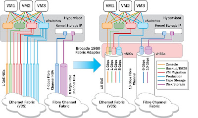
Each port on the Brocade 1860 can be configured in any of the following modes:
  • HBA mode: Appears as a FC HBA to the OS. It supports 16/8/4 Gbps FC when using a 16 Gbps SFP+ and 8/4/2 Gbps when using an 8 Gbps SFP+. In FC mode N_Port trunking can aggregate two 16 Gbps Fibre Channel links into a single logical 32 Gbps link with frame-level load-balancing for the highest levels of link utilization and transparent, automatic failover and failback for high availability.
  • NIC mode: Appears as a 10 GbE NIC to the OS. It supports 10 GbE with DCB, iSCSI, and TCP/IP simultaneously.
  • CNA mode: Appears as two independent devices, a Fibre Channel HBA (using FCoE) and a 10 GbE NIC to the OS. It supports 10 GbE with DCB, FCoE, iSCSI, and TCP/IP simultaneously.
Brocade vFLink technology allows a single Brocade 1860 Fabric Adapter to logically partition a physical link into as many as eight virtual fabric links (vFlinks) per port. This is achieved by replicating the adapter at the PCIe bus level and presenting multiple PCIe physical functions (PFs) to the OS layer. The OS not need to have any special support for vFLink; it will just see each vNIC or vHBA as a separate physical I/O device, and it will know how to operate it as long as the appropriate driver is present. When configured as 16 Gbps Fibre Channel, a single physical port can support up to eight vHBAs. When configured as 10 GbE, a physical port can support any combination of up to eight vNICs and vHBAs. In this case, vHBAs are achieved by using FCoE protocol.


Direct I/O removes the hypervisor involvement in I/O processing and enables near-native performance for those VMs. However, directly assigned I/O devices cannot be accessed by more than one VM at a time, thus requiring dedicated hardware resources. I/O virtualization technologies like vFLink can help alleviate this problem by logically partitioning the adapter and directly mapping vNICs or vHBAs to VMs, enabling a better sharing of physical adapters with direct I/O.


Single-Root I/O Virtualization (SR-IOV) allows a PCIe device to be virtualized, by introducing the concept of PCI virtual functions (VFs) - lightweight PCI functions that can be used only to move data in and out of the device, and that have a minimum set of configuration resources. VFs can be directly mapped to virtual machines using direct I/O technology, while the hypervisor retains control of the PF, which requires what is called a “split-driver” model.

By implementing Virtual Machine Optimized Ports (VMOPs), the Brocade 1860 leverages hypervisor multi-queue technologies such as VMware NetQueue and Microsoft VMQ to offload the incoming network packet classification and sorting tasks from the hypervisor onto the adapter, freeing the CPU and enabling line-rate performance.
Virtual Ethernet Bridge (VEB) inside the I/O adapter offloads Inter-VM traffic switching. The adapter is responsible for providing both inter-VM and inbound/outbound communication. Packets are switched directly in the adapter with no hypervisor involvement, providing high performance, low latency and low CPU utilization. No special support is required from the access layer switch, since inter-VM traffic continues to be switched inside the server.
Virtual Ethernet Port Aggregator (VEPA) extends network connectivity all the way to the applications, making VMs appear as if they were directly connected to the physical access layer switch. All VM-generated traffic is sent out of the adapter to an external switch, essentially moving the demarcation point of the network back to the physical access layer. The external switch can then apply filtering and forwarding rules to the VM traffic, and it can also account for and monitor the traffic with the same management tools that network administrators are accustomed to.
Multi-channel VEPA is an additional enhancement to VEPA to allow a single Ethernet connection to be divided into multiple independent channels, where each channel acts as a unique connection to the network. The benefit of multi-channel VEPA is that it allows a combination of VEPA for VMs where strict network policy enforcement and traffic monitoring is important, and hardware-based VEB for high-performance VMs where minimal latency and maximum throughput is a requirement.
Edge Virtual Bridging (EVB) defines the standard for VEPA and the Virtual Station Interface Discovery Protocol (VDP)—sometimes referred to as Automatic Migration of Port Profiles (AMPP)—that can be used to automatically associate and de-associate a VM to a set of network policies, sometimes referred to as “port profile.”
In traditional virtualized environments, management of physical and virtual networking is fragmented, as the software vSwitch is typically managed by the server administrator, whereas the physical network is managed by the network administrator. The network administrator has no visibility into the software switch management, and is unable to enforce networking policies on inter-VM traffic within a physical host. By offloading the switching from the hypervisor onto the adapter or the access layer switch, management of physical and virtual switching can be unified under a single management application by the network administrator.

Emulex also announced XE201 I/O controller (only controller, not host adapter!), which provides a combination of up to four ports of native 8 and 16Gb/s FC, FCoE, iSCSI, RDMA over Converged Ethernet (RoCE), 10 and 40Gb/s Ethernet.
XE201 supports a wide range of new features for both server initiator and storage target modes, including:
End-to-end data integrity with BlockGuard™ offload eliminates silent data corruption as data traverses the system from the O/S all the way to the disk array.
vScale™ workload-based performance and scalability—multi-core ASIC engine with eight cores, running a combination of standard protocols and specialized functions
vScale resource pooling—dynamically allocates resources to multiple protocols, enabling scale-up of up to 256 VMs (255 virtual functions [VF] + 1 physical function [PF]), 2000 simultaneous TCP/IP sessions
vEngine™—I/O offload lowers CPU burden on host server, enabling support for more VMs
vPath™ virtual I/O capability supports emerging I/O virtualization standards including Single Root I/O Virtualization (SR-IOV), Virtual Ethernet Port Aggregator (VEPA) and Virtual Ethernet Bridge (VEB), all of which are supported by an internal Emulex Ethernet switch that allows data to be forwarded between VMs, which are collocated on same server, without travelling to an external switch for higher performance and ensuring traffic isolation


And what will Qlogic answer?